 |
 |
|
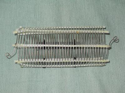
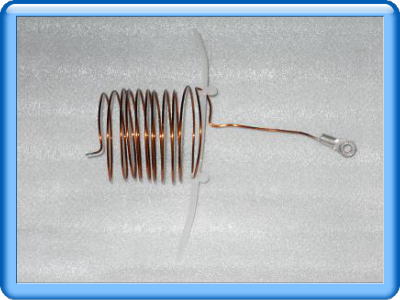
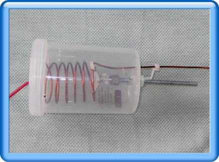
Coil like a spring
|
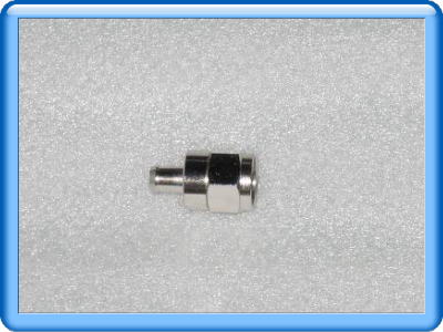
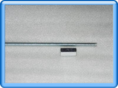
Long nut on a bottom of case
|
| |
|
| |
|
 |
 |
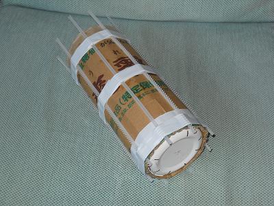
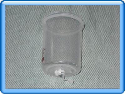
Case with nut
|
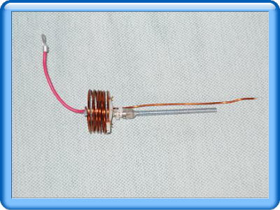
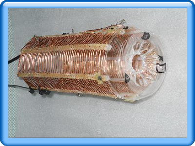
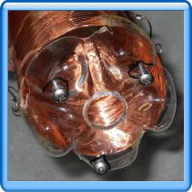
Coil with F connector and long bolt
|
| |
|
| |
|
 |
 |
|
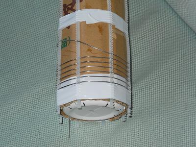
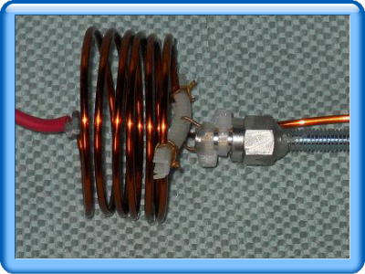
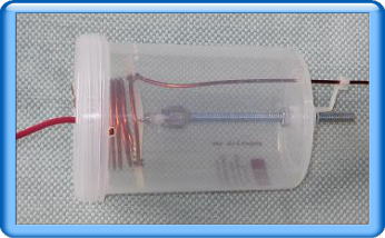
Close up of coil, F connector and bolt whici is fixed by epoxy adhesive
material
|
| |
|
| |
|
 |
 |
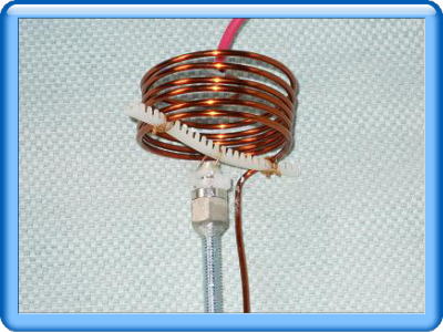
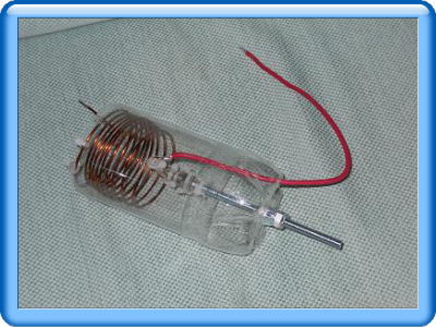
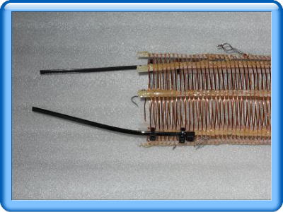
Strectched coil which is less inductanace
|
Shurinked coil which is much more inductance than left one |
| |
|
| |
|
 |
 |
|
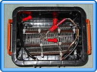
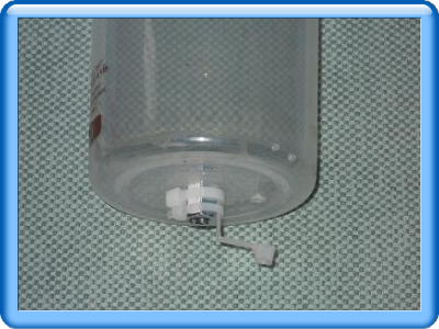
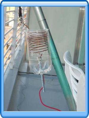
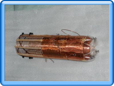
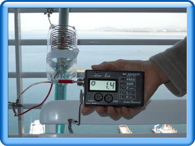
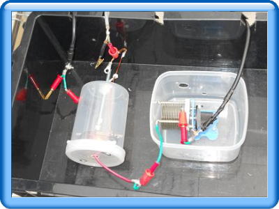
Variable L in a PET bottle
|
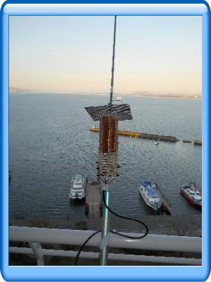
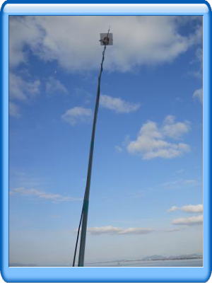
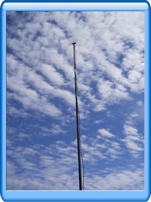
Variable L with fishing rod
at balcony of the hotel
|
| |
|
| |
|
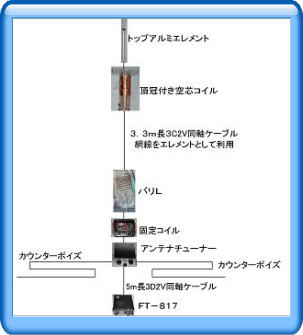
How to make a top coil and capacitance hat for 160m band
|
I rolled 2mmφ enameled wire on a plastic bottle about 123 turns and then 28 turns of spiral coil which is 65mmφ diameters coil.
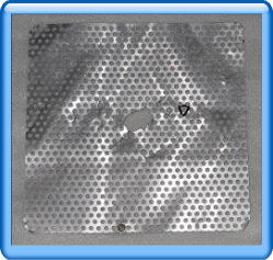
And then attached with punched thin alminum board on the bottle.
|
| |
|
 |
 |
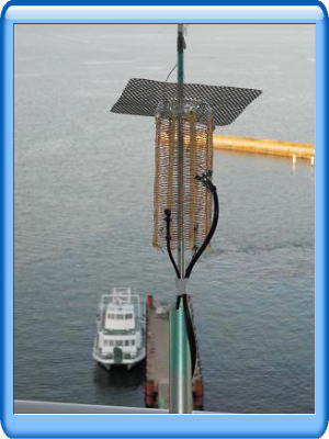
Punched alminium thin
board for capacitance hat
|
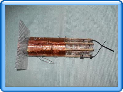
Coil for 160m band with taps
for 80m 40m and 30m bands
|
| |
|
| |
|
 |
 |
Coil for 40m/30m bands
|
Coil with INSULOK |
| |
|
| |
|
 |
 |
3 screws for capacitance hat
for 160m band |
Coil and capacitance hat
|
| |
|
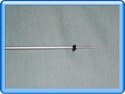
Top element
|
|
|
I adjust element length with 2 diameters alminum pipes which pipes change
resonant frequency widely.
|
 |
 |
2 alminum pipes with black clump
|
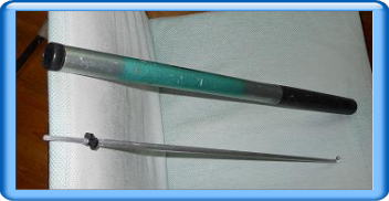
Fishing rod and almimum element |
| |
|
| |
|
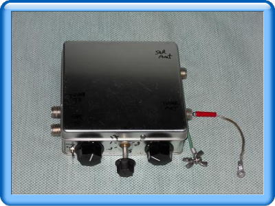
| Manual AT tuner |
|
| |
|
 |
 |
SWR meter and AT tuner
|
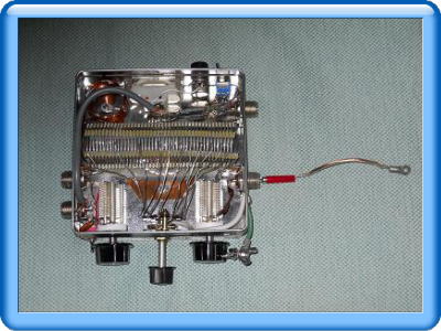
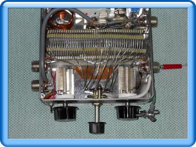
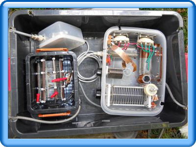
Inside of SWR meter and tuner
|
| |
|
| |
|
 |
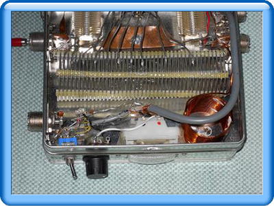 |
Coil and SW with VC
|
SWR circuit(front of box)
|
| |
|
| |
|
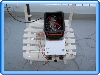
Variable coil, AT tuner with SWR meter |
| |
|
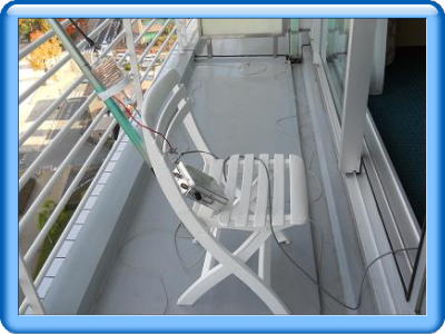
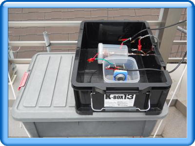
Setting antenna and adjustment
|
|
|
I attached top element, top coil, 3.3m coxial element, side of fishing rod and then installed valiable L, bottom coil, CP and AT tuner.
.
Adjust frequency about 1.910MHz by top element and bottom coil and then adjust frequency 1.9075MHz to 1.9125MHz for Japanese domestic operation frequency by valiable L exactly.
|
| |
|
| |
|
 |
 |
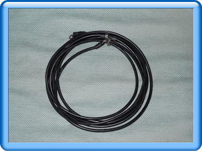
3.3m 3C2V antenna element
|
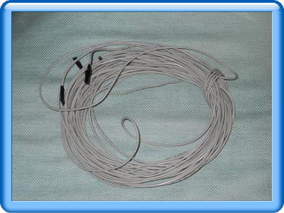
2 of CP(40m lengh)
|
| |
|
| |
|
 |
 |
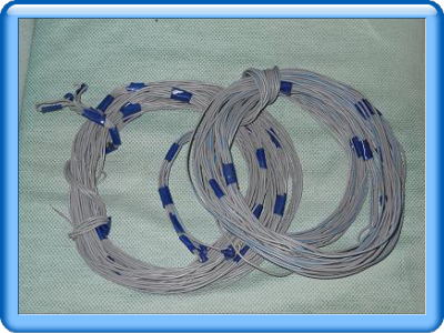
2 of 5m CP for 7/10MHz bands
|
Antenna with hat and top coil
|
| |
|
 |
 |
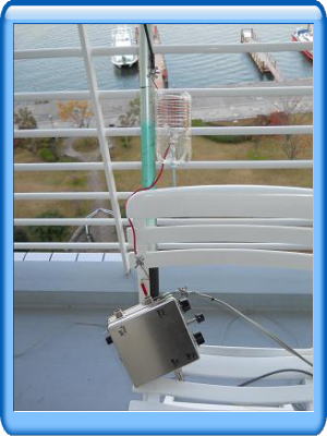
AT tuner and CP for 7MHz band
|
Adjust SWR by valiable coil
|
| |
|
| |
|
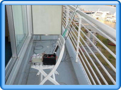 |
CP, bottom coil for 160m band
and AT tuner on a chair
|
| Efficiency of antenna system and receiving noise |
| |
|
|
Efficiency of Antenna system is very important for QRP operation.
I have to be resonate antenna system by top element coxial element bottom and valiable coi and CP and then impedance matching to SWR 1:1.
Above anetnna system has very narrow band width(about 10KHz widths with SWR 1:1.5) and this antenna has very low noise.
I think that antenna with narrow band width is one of good BPF for noise supression.
|
| |
|
| |
|
| Result |
|
| |
|
|
I operated 1.9MHz band and 7MHz band in Okinawa Island southern part of Japan.
Many stations called me on 40m band.
I contacted with station of Kyushu Island from Okinawa on 1.9MHz band.
But my power surply was out of date after above contact was end.
On the other hand,
I contacted with 10 stations on 40 meters band at the hotel beside Biwako lake in Shiga prefecture and 10 stations on 160 meters band within a hour.
I was very happy to contact with above stations with small antenna and QRP without JA2, JA6, JA8.
I have to do operation maxuimam 2 hours a day because my XYL don't like operation for my Ham radio at resort hotels everywhere.
But above negotiations is very usefull to keep good relationship between the two.
|
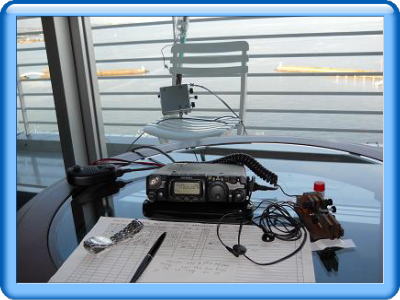 |
 |
FT-817 and key
|
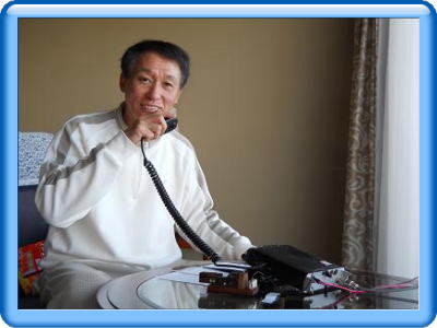
SSB operation
|
| |
|
| |
|
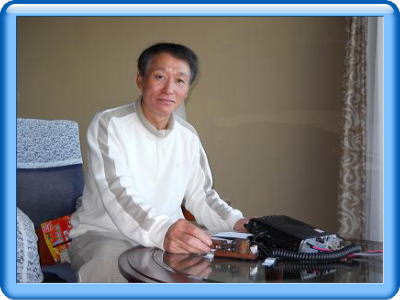 |
CW operation
|
| |
|
| |
|
| Conclusion |
|
|
I am operating from 1.8MHz to 10MHz band as similar antenna system at my home.
My antenna system for 7 and 10 MHz band is that I install 10m long fiber rod with capasitance hat, antenna element, variable coil and CP system at the rooftop of my house.
VC is for 10MHz band resonant.
Additinal element to Groud level for 80m band and 160m band with bottom coil and CP system, and then connect with CG5000 automatic antenna tuner which works 800W.
|
| |
| |
 |
 |
10m long fiber rod
with capacitance hat
|
Change frequency
(7or10MHzband) by banana chip |
| |
|
| |
|
 |
 |
Valiable coil and VC for 10m band
CG5000 is under a black
|
Bottom coil with another manual
ntenna tuner on the ground
|
| |
|
|
I enjoy Ham radio from QRP operation to 1KW one
I contacted with ZL8X on 160 and 80m bands on Nov.2010 above antenna system with FT-1000MP MARK5, bearfoot 200W.
Finaly I am very happy to contribute my experience for your ham radio life.
|

 [
[